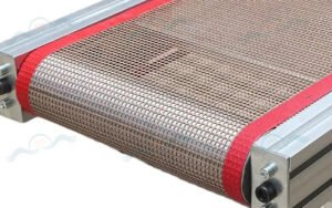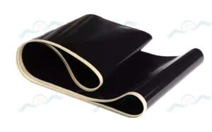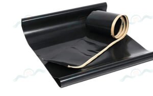
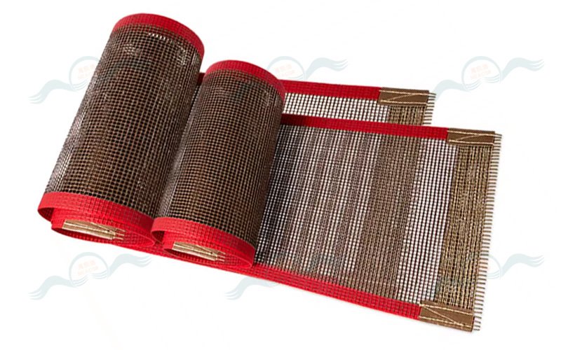
Determining Whether a PTFE Conveyor Belt Is Tracking Off-Center: Stopped Static Inspection Combined with Dynamic Running Observation
Determining whether a PTFE conveyor belt is experiencing tracking deviation centers on two core activities: stopped static inspection and dynamic running observation. Given PTFE belts’ lightweight, thin, and highly flexible material characteristics (compared to rubber belts, even minor tension imbalance or installation deviation easily causes tracking deviation), assessment focuses on three core dimensions: centerline offset, edge contact status, and running trajectory — while distinguishing between “false tracking deviation (e.g., off-center material loading)” and “true tracking deviation (belt or equipment issue).”
Ⅰ. Stopped Static Inspection — Identify Installation and Foundational Deviation Risk
After stopping and disconnecting power, inspect the belt in its unloaded, stationary state to identify frame and roller/idler installation deviations (the root cause of tracking deviation and the basis for determining “whether continuous tracking deviation will occur”). Check 3 key points:
Belt Natural Centering: The PTFE belt should naturally align with the centerline of the drive roller, tail roller, and idler rollers — no single-side edge contact or belt edge overhanging beyond rollers
Roller / Idler Parallelism: All roller (drive/tail) and idler axes must be perpendicular to the frame; no height difference between the two ends of any single roller/idler. If one side is misaligned, the belt will shift toward the misaligned side even in the static state
Frame Level & Symmetry: No left-right tilt or deformation; tensioning device adjustment (e.g., tensioning screws) must be equal on both sides; PTFE belt tension must be balanced on both sides — no single-side slack or over-tightness
Acceptance Criteria: If the belt deviates from the roller/idler centerline by more than 3 mm in the static state, or if one side’s edge presses against the roller side wall, a foundational tracking deviation risk exists — dynamic tracking deviation will almost certainly occur after starting.
Ⅱ. Core Dynamic Running Observation — No-Load First, Then Loaded (Most Critical Step)
PTFE belt tracking deviation only fully manifests during operation. No-load deviation indicates equipment issues; loaded deviation requires distinguishing between material-related external causes and equipment-internal causes. Always test no-load first, then loaded to avoid misdiagnosis. Observe 4 core points, using the frame centerline / roller centerline as the reference baseline:
1. Observe Belt Centerline Offset (Most Direct Core Assessment)
Mark the frame centerline with chalk at the entry, middle, and exit positions on both sides of the frame. During operation, observe the alignment between the belt’s longitudinal centerline and the frame centerline:
| Condition | Offset Range | Description |
|---|---|---|
| No deviation | ≤ 5 mm; no fixed-direction continuous offset | Minor oscillation < 3 mm is normal |
| Minor deviation | 5–10 mm, continuous single-side offset | No edge contact with frame or guards |
| Moderate deviation | 10–20 mm | Belt edge occasionally contacts frame side plate/guard; no obvious scraping |
| Severe deviation | > 20 mm | Belt edge continuously scrapes frame, guards, or guide plates; edge lifting, folding, or jamming may occur |
2. Observe Belt Edge Contact Condition (PTFE Belt-Specific Focus — Easily Damaged)
PTFE belt edges lack the rubber belt’s wrapped wear-resistant edge layer — scraping easily causes edge cracking and delamination:
- No deviation: Edge maintains 5–10 mm safe clearance from frame, guards, and guide plates throughout — no contact
- Deviation present: Edge continuously or frequently presses against or scrapes these components; on curved sections (if present), edge contacts the curve roller; visible friction marks appear (e.g., edge whitening, fraying)
3. Observe Running Trajectory Abnormalities
A properly running PTFE belt should move at constant speed in a straight line, with no snaking or slip-induced offset:
- Snaking: Left-right oscillation > 5 mm; typical of minor deviation (usually caused by unequal tension or slightly misaligned idlers)
- Fixed single-side offset: Continuous offset to left or right with no self-correction; indicates moderate to severe deviation (usually caused by roller misalignment or tensioning device maladjustment)
- Slippage + offset: Belt slips at drive roller and deviates to one side simultaneously; usually caused by worn roller lagging or insufficient belt tension
4. No-Load vs. Loaded Comparison — Distinguish False vs. True Tracking Deviation
If material is off-center during loaded operation, the belt experiences unilateral force and deviates — this is false tracking deviation (not a belt/equipment problem) and must be distinguished from true tracking deviation:
- True tracking deviation: Continuous single-side offset even under no-load; worsens under load; deviation persists even with centered material loading
- False tracking deviation: No deviation under no-load (centerline aligned); deviation only under load; deviation direction matches material offset direction (e.g., material left-biased → belt drifts left); deviation disappears when material is centered
Ⅲ. Simple Auxiliary Detection Methods — For High-Precision or Continuous Operation Scenarios
Marking Alignment Method: Draw a perpendicular alignment mark on the belt side (non-working surface) and a corresponding mark on the frame. During operation, observe whether both marks remain aligned — continuous misalignment indicates tracking deviation; the misalignment distance is the offset amount.
Limit Switch Sensing Method: Install simple photoelectric sensor strips or mechanical limit stops at safe positions along both sides of the belt edge. If the belt drifts enough to trigger the sensor/stop, tracking deviation is confirmed (suitable for automated production lines with alarm integration).
Ⅳ. Special Judgment Notes for PTFE Conveyor Belts
Due to PTFE belts being thin, flexible, and exhibiting noticeable thermal expansion/contraction, avoid 2 common misdiagnosis errors:
Thermal Expansion in High-Temperature Conditions: PTFE belts undergo slight thermal expansion in drying and heat conveying applications, which may cause minor oscillation. If the belt returns to center after cooling, this is normal — not tracking deviation.
Effect of Splice Joint Misalignment: If the PTFE belt splice joint was cut non-perpendicularly or bonded with offset alignment, a brief deviation occurs each time the joint passes over a roller. If the belt returns to center after the joint passes, this is normal — if deviation persists throughout, it is true tracking deviation.
Summary: Field Rapid Assessment Procedure
- Stopped static inspection: Check belt centering; verify roller/frame installation; identify foundational risks
- No-load running observation: Check centerline offset, edge contact, and snaking trajectory; determine if true tracking deviation exists
- Loaded running verification: Compare with no-load state; distinguish true tracking deviation from false deviation caused by off-center material loading
- Quantified measurement: Use marking method to measure offset magnitude; classify deviation severity (minor/moderate/severe)
Following this procedure enables rapid, accurate determination of whether a PTFE conveyor belt is experiencing tracking deviation, while also providing preliminary cause identification as the basis for subsequent correction measures.