How to Adjust the Tension of PTFE Conveyor Belts?
The core principles for PTFE conveyor belt tension adjustment are: small incremental steps, synchronized adjustment on both sides, precise measurement, and load verification. Tension range is typically controlled at 15–25 N/cm of belt width, avoiding both excessive slack (slippage) and excessive tightness (belt and equipment damage).
Ⅰ. Assessing Tension Condition (Required Before Adjustment)
| Condition | Symptoms | Impact |
|---|---|---|
| Too Loose | Excessive belt sag (> 3% of idler spacing); drive drum slippage; tracking deviation; high vibration | Low conveying efficiency; accelerated wear; material spillage; motor overload |
| Too Tight | Belt surface taut with no sag; bearing “humming” noise; edge stretch cracking; splice joint failure | Shortened service life; increased energy consumption; bearing damage; frame deformation |
| Proper | No-load sag of 1.5%–2% of idler spacing; no slippage under load; smooth operation with no abnormal noise | Extended service life; efficient conveying; moderate energy consumption; stable equipment |
Quick Assessment Method: Apply 5 kg pressure at the midpoint between two idlers — sag should meet the above criteria. Where possible, measure directly with a tension meter; recommended value for PTFE belts is 15–25 N/cm (e.g., for a 300 mm belt width, total tension 450–750 N).
Ⅱ. Adjustment Methods for Common Tensioning Devices
1. Screw-Type Tensioning Device (Most Common)
- Stop equipment and disconnect power; ensure safety
- Loosen the fastening bolts on the tensioning roller bearing housing
- Synchronously adjust both side adjustment screws (half to one turn per adjustment to avoid tracking deviation): clockwise increases tension; counterclockwise decreases tension
- Check roller parallelism after adjustment; left-right tension differential ≤ 5%
- Tighten fastening bolts; manually rotate the belt to check flexibility
- Conduct no-load trial run; observe sag and tracking deviation; fine-tune as needed
2. Counterweight Tensioning Device
- Verify counterweight is vertical, free of offset, with weights securely fixed
- Insufficient tension: add counterweight incrementally (+5% per step, avoiding overload); maintain balance on both sides
- Excessive tension: reduce counterweight; synchronously adjust both side balance
- After load testing, confirm no slippage between belt and roller
3. Tensioning Roller Adjustment
- Loosen tensioning roller fastening screws
- Adjust roller position (move away from drum to increase tension; move closer to decrease tension)
- Check belt tension uniformity after fixing
- Note: Use tensioning rollers cautiously with PTFE mesh belts — prone to localized damage
4. Hydraulic / Pneumatic Tensioning Device
- Adjust pressure progressively via the control system
- Monitor tension value in real time; lock once within the target range (15–25 N/cm)
- Automatic tensioning systems require periodic calibration to ensure accuracy
Ⅲ. Complete Adjustment Procedure (General Workflow)
1. Preparation
- Disconnect power and apply lockout tags for safety
- Prepare tools: wrench, tension meter, tape measure, level, marker pen
- Clean belt and roller surfaces; remove oil and debris
2. Initial Adjustment
- Determine adjustment direction based on current condition (increase/decrease tension)
- Apply the corresponding tensioning device method for initial adjustment, reaching 70%–80% of target tension
3. Parallelism Calibration (Critical Step — Prevents Tracking Deviation)
- Use a level to check roller-to-frame perpendicularity
- Ensure the roller axis is perpendicular to the belt travel direction after adjustment
- Left-right tension differential must be controlled within 5%
4. No-Load Test (15–30 Minutes)
- Start equipment; observe belt running condition
- Check sag: should be 1.5%–2% of idler spacing under no-load conditions
- Observe tracking deviation; fine-tune as necessary (principle: tighten the side toward which the belt drifts)
5. Load Verification (30–60 Minutes)
- Apply 80%–100% of rated load; distribute material evenly
- Check drive drum for slippage marks; confirm belt runs smoothly
- Measure motor current; ensure no overload condition
- For applications with significant temperature variation (PTFE belts commonly used in high-temperature environments), re-verify tension at operating temperature
6. Lock & Document
- Once tension is confirmed appropriate, tighten all adjustment bolts
- Record adjustment date, tension value, and adjustment amount for maintenance records
Ⅳ. Special Situation Handling
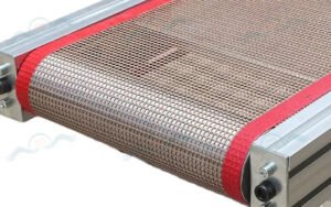
1. PTFE Mesh Belt Adjustment Considerations
- Avoid excessive localized stress to prevent mesh deformation
- Tension should be slightly lower than for solid belts; recommended value 15–20 N/cm
- After adjustment in high-temperature operating conditions, re-verify tension once cooled (accounting for thermal expansion/contraction)
2. Splice Joint Protection
- Avoid concentrating tension at the splice joint area during adjustment to prevent adhesive failure or fracture
- If the joint is damaged, repair it before adjusting tension
3. Adjustment After Long-Term Use
- PTFE belts have low elasticity and dimensional stability — minimal elongation after long-term use
- If significant slack appears, inspect for damage first before applying tension compensation
- After adjustment, run for 2 hours; if abnormal wear is observed, reduce tension by 10%–15%
Ⅴ. Maintenance Recommendations
- Regular Inspection: Visual inspection of tension condition daily; precise measurement with tension meter weekly
- Cleaning & Maintenance: Keep belt and roller surfaces clean; avoid oil contamination affecting friction coefficient
- Temperature Monitoring: In high-temperature environments, periodically check tension changes and adjust promptly
- Record & Analysis: Establish a tension adjustment log; analyze trends to optimize maintenance intervals
PTFE conveyor belt tension adjustment must follow the principles of precise measurement, synchronized adjustment, and load verification — controlled within 15–25 N/cm of belt width with left-right tension differential ≤ 5% — to achieve optimal operating condition, extend service life, and ensure equipment safety.